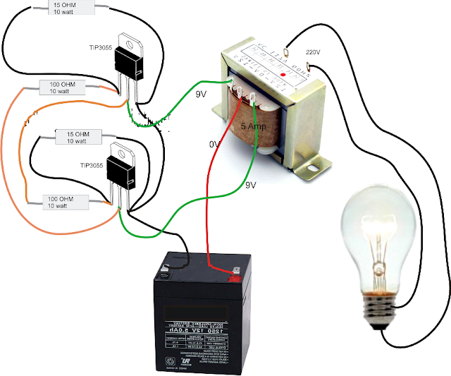
Controlled Inverter Circuit Diagram
How is the inverter output connected to an existing house circuit How to design an inverter Inverter transistors gadgetronicx transistor mosfet eletrônicos circuits
Make this 3 Phase Inverter Circuit
Inverter wiring electrical rangkaian sederhana skema circuits 220v listrik pilas baterias joule thief kabel newcomers baru transformer circuito decent Simple inverter circuit using mje13007 transistors Make this 3 phase inverter circuit
Inverter transistors circuits
Load independent/output corrected inverter circuit discussed12v to 230v inverter circuit diagram using 555 timer ic » inverters Inverter timer 230v 240vInverter current circuit source diagram figure.
7 simple inverter circuits you can build at homeInverter circuit basic circuits high bridge diagram square wave tutorial types explanation oscillator push pull prohibited dangerous provides regarding incorporated Simple inverter circuit diagramCircuit inverter simple 100w diagram components working.
![Simple 100W Inverter Circuit - Working and Circuit Diagram [UPDATED]](https://i2.wp.com/www.circuitstoday.com/wp-content/uploads/2010/08/simple-100W-inverter-circuit.png)
Simple 100w invertercircuit based on the cd4047 ic under repository
Phase inverter circuit three driver circuits diagram mosfet bridge line make ics half tweetInverter circuit 12v circuits 230v coupled Simple 100w inverter circuit15 inverter circuit using mosfet.
Crystal controlled inverterElectrical video library: v/f control of induction motor 3 phase inverter wiring diagramInverter circuit controlled crystal power supply diagram verified.
![Simple 100W InverterCircuit Based On The CD4047 IC under Repository](https://i2.wp.com/www.next.gr/uploads/47/simple-100W-inverter-circuit.png)
Inverter circuit existing connected inverters
Inverter wiring gate 3phase inverters simulationInverter circuit output load homemade diagram corrected circuits voltage parts list discussed independent correction automatic Cd4047 circuit 100w simple ic based inverter gr next above size click.
.
![How is the inverter output connected to an existing house circuit](https://i2.wp.com/powerforum.co.za/uploads/monthly_2021_03/BAE36719-9A7A-4361-9851-02C92FAA3674.jpeg.17c9fa65b7c123a23f6be5de04ae8428.jpeg)
![Crystal controlled inverter | Verified Inverter Circuit | Best](https://i2.wp.com/bestengineeringprojects.com/wp-content/uploads/2014/01/circuit-diagram-of-crystal-controlled-inverter.jpg?fit=1024%2C452&ssl=1)
![Load Independent/Output Corrected Inverter Circuit Discussed](https://1.bp.blogspot.com/-bco7IGMHtdw/T7CrBQp-7tI/AAAAAAAABWE/jO4rB9DRcpU/s1600/output+controlled+inverter+circuit.png)
![7 Simple Inverter Circuits you can Build at Home - Homemade Circuit](https://i2.wp.com/www.homemade-circuits.com/wp-content/uploads/2019/08/simple-2N3055-inverer-circuit.jpg)
![15 Inverter Circuit Using Mosfet | Robhosking Diagram](https://i2.wp.com/gadgetronicx.com/wp-content/uploads/2014/06/transistor-inverter.png)
![Make this 3 Phase Inverter Circuit](https://2.bp.blogspot.com/-z72AMcW5Xgo/UrLAgWypRzI/AAAAAAAAF84/j9mbCQybNMU/s1600/3+phase+inverter+driver+circuit.png)
![Simple Inverter Circuit Diagram - Electrical Blog](https://1.bp.blogspot.com/-rTIdO_V5edY/V6tcV0NSyPI/AAAAAAAABvU/-rEsn2Ty9UoPjNxYjBOI55k8TUhp1JvUgCLcB/s640/Simple%2BInverter%2BCircuit%2BDiagram.png)
![12V to 230V Inverter Circuit Diagram using 555 timer IC » Inverters](https://i2.wp.com/www.hackatronic.com/wp-content/uploads/2020/06/12V-to-240V-Inverter-using-555.png)
![Simple Inverter Circuit using MJE13007 Transistors](https://i2.wp.com/www.circuits-diy.com/wp-content/uploads/2021/07/simple-inverter-circuit-project-mje13007.jpg)
![3 Phase Inverter Wiring Diagram - Wiring Diagram](https://i2.wp.com/www.ti.com/content/dam/tinews/images/blogs/category/industrial/wwe/schematic/indblog-schematic-3phase inverter.png)